Introduction
The advent of hand-held radio remote control consoles significantly improved the safety and productivity of track-mounted tunneling vehicles such as road headers and drum-type continuous miners. The radio remote console affords the operator improved visibility while allowing the machine to be controlled from a much safer location, several meters behind the cutting workings.
In the case of road headers and bolter miners, local visual control of the machine does not completely overcome the challenges of maintaining the correct machine position, tunnel heading, and cutting profile.
Typically, manual surveying methods are necessary that are both time-consuming and offer poor accuracy in precision tunneling applications. The dangers of some mining conditions also require the operator to be much further removed from the machine. For example, in situations when cutting activity suddenly exposes pockets of pressurized underground gas; causing a so-called “outburst” event where large pieces of rock – and even the machine itself – can be pushed violently backward.
To address both accurate machine tunnel positioning and worker safety - Pempek has developed the Flameproof Tunneling Guidance System.
The system allows the machine to be monitored, positioned, and controlled – safely and efficiently – from a mobile control station located up to several hundred meters away from the cutting face. The control station features several LCD monitors;
providing streaming video and machine navigation information.
A real-time graphical representation of the machine cutter head makes it easy for the operator to cut the correct tunnel profile.
Unlike many other solutions already available for tunneling applications – the Pempek solution carries flameproof (Ex d) certification; allowing deployment in coal and potash mining applications.
System Overview
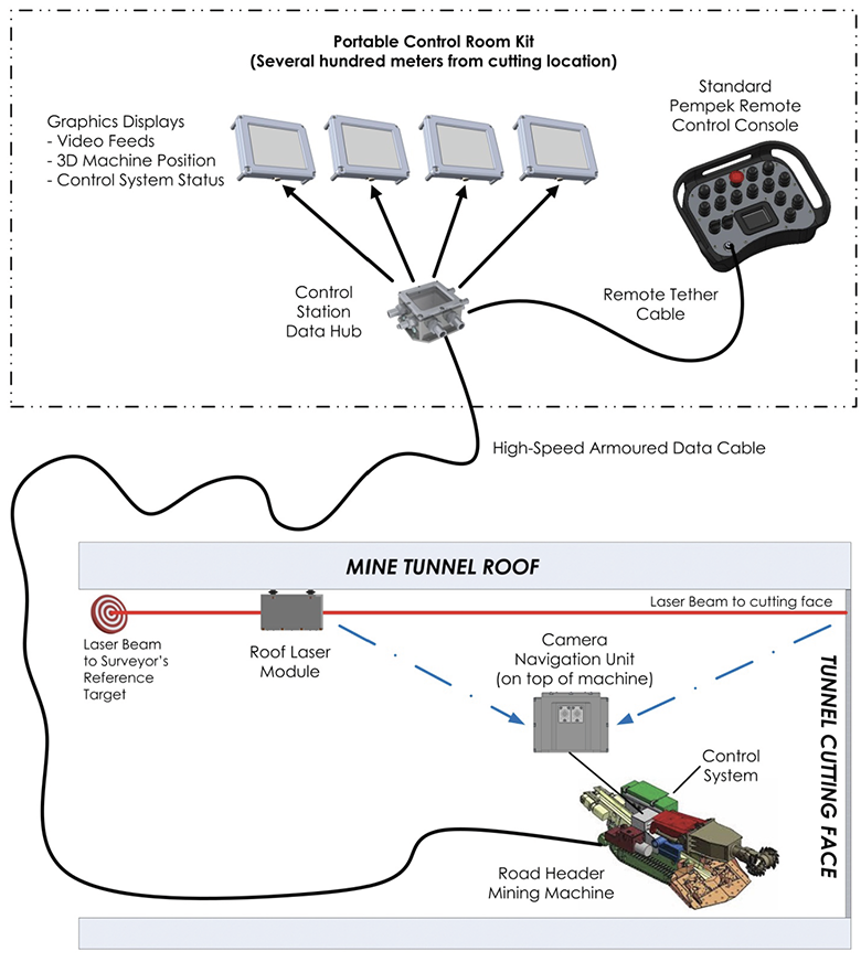
A general overview of the tunneling guidance system is shown in the above image.
The system is composed of five main systems:
(1) Roof Laser Module (L0YP)
(2) Machine Control System (Pempek OBP-PLUS )
(3) Laser Navigation Module (L0XP)
(4) Portable Control Room Kit
(5) Telemetry System (ROYCE)
Roof Laser Module (L0YP)
Laser-guided surveying is a technique already commonly used in mining and tunneling industries.
A laser source is typically installed by surveying staff on the tunnel ceiling, behind the cutting machine.
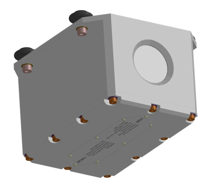
Pempek has developed its own laser module, incorporating two laser sources (one front-facing and one rear-facing) as well as an internal battery pack. The module also carries flameproof (Ex d) certification. The front-facing laser source projects a beam onto the cutting face so that it can be tracked in real-time by the machine-mounted Laser Navigation Module (L0XP).
The rear-pointing laser can be used by surveying staff to reference a geologically stable target further back in the tunnel so as to correct for any small subsidence of the roof whilst cutting.
Machine Control System (Pempek OBP-PLUS )
The machine control system controls and monitors all the main machine functions; including hydraulic actuators, electric motors, and sensors. The system also provides for local radio remote control, when combined with any model of Pempek standard remote control console.
Laser Navigation Module (L0XP)
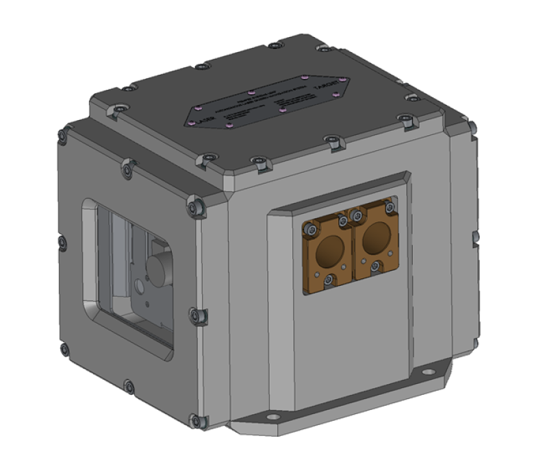
To support control room mining, only one additional item of machine-mounted equipment is necessary. The Laser Navigation Module (L0XP) is a flameproof certified (Ex d) box that must be installed on top of the machine frame.
The module includes a pair of high-resolution digital camera sensors – one looking forward to the cutting face and one looking backward. The cameras are used by the navigation system to track the position of the roof-mounted laser. The laser can be seen as it hits the cutting face. The source of the laser (in the back of the tunnel is also visible).
Using real-time image tracking of the laser position – coupled with feedback from the internal inclinometer and gyroscope sensors - the module continuously calculates the position of the cutting machine within the tunnel. The positional information calculated includes the absolute position coordinates in space (x, y, and z axes) as well as the rotational pose of the machine (pitch, roll, and yaw).
Portable Control Room Kit
The Portable Control Room Kit includes a set of LCD displays and cabling that can be quickly relocated and assembled to provide a mobile control station at any location within the mine.
Patch cables between the modules support rapid connection and disconnection. The complete control room equipment can be re-connected in a matter of a few minutes.
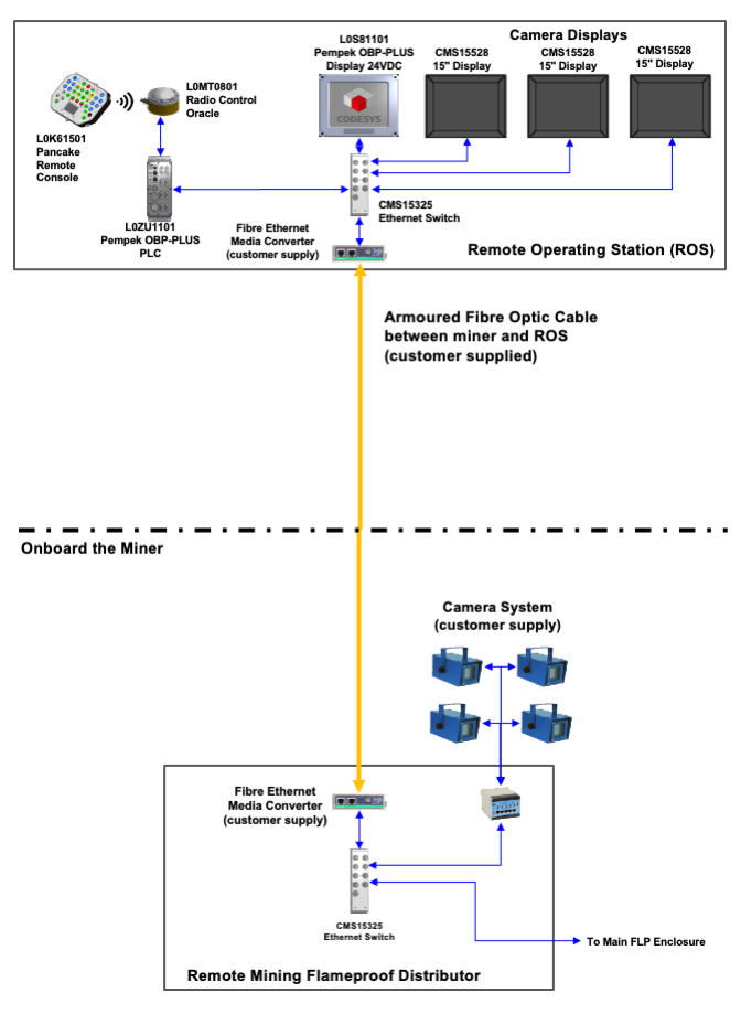
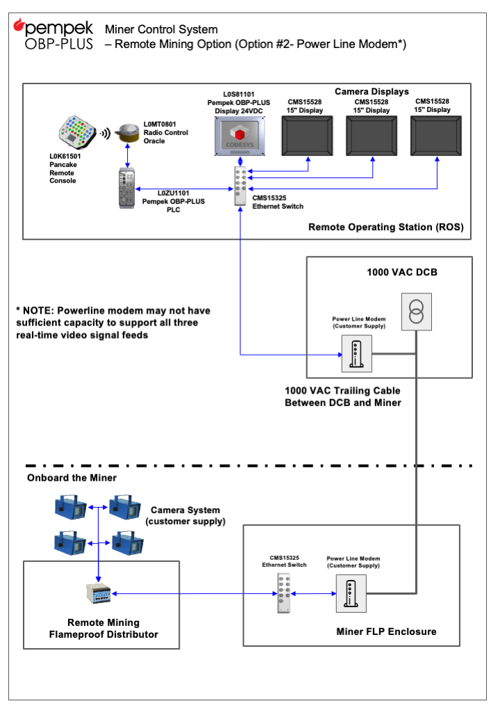
A high-speed data connection (typically an armored fibre-optic cable; or another network pathway) as shown in figures 11 or 12 connects to the Data Hub Module. The Data Hub then connects to the set of LCD screens.
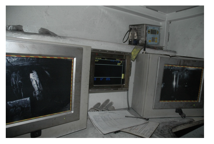
The Data Hub maintains real-time communication with the machine control system, via the high-speed data connection. This pathway allows the streaming video and navigation information to be constantly updated to the LCD screens. One example of the underground control room installation (where screens have been installed in a semi-enclosed cabin) is shown.
The standard remote control console also plugs directly into the Data Hub to allow the operator control of the machine.
The use of the same remote control console for both local machine operation and tele-remote outburst mining mode is a key advantage of the Pempek product. The operator only needs training and
familiarisation with one format of machine control.
Telemetry
The collection of machine operational data (Telemetry) is an essential part of the mining process.
Data collection and analysis provide significant benefits and improves production and maintenance activities.
The Pempek control system (Pempek OBP-PLUS ) integrates directly with the Pempek ROYCE telemetry system.
Operating Modes
The complete system provides three modes of
machine operation:
1. Local Radio Remote Control
2. Control Room Remote Control
3. Auto Profile Cut
Local Radio Remote Control
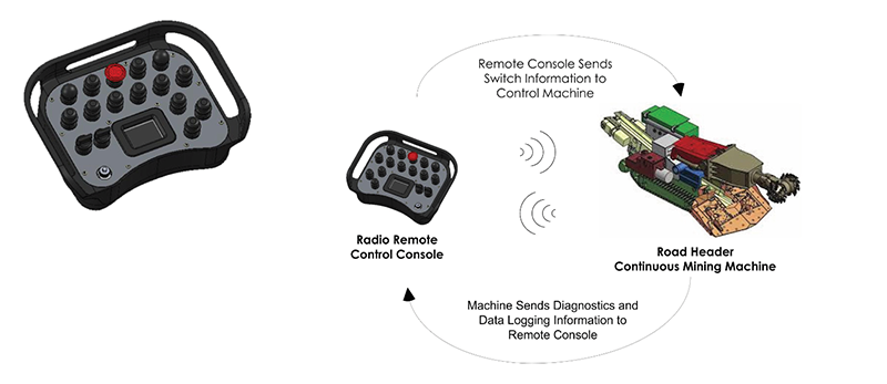
The simplest form of control is for the operator to use the remote console in radio mode and control the machine using the radio signal. This requires the operator to remain within a line-of-sight distance of the machine; in order to maintain an adequate radio signal. This form of control is illustrated.
In this mode of control, the keypress control
actions of the operator are transmitted, via radio data signal, to the machine. The machine also sends diagnostic and data logging information back to the remote console. The built-in graphics display on the remote console allows key machine parameters and performance diagnostics to be monitored without the need for the operator to
approach the machine.
Control Room Remote Control
This mode of control is typically used when there is a risk of dangerous mining conditions such as outbursts or roof collapse. In the event of an accident, the operator is located in a safe zone, far removed from the potential hazards. The operator can use the same radio remote control handset to control the machine from the remote control room station.
In this mode of control, a tether cable is used to connect the remote console to the Station Data Hub. The Data Hub is then connected to the machine under control using a special armored data cable up to several hundred meters in length.
Graphics LCD panels are also connected to the Data Hub to provide video and machine position feedback to the operator. The operator controls the machine using the same control switch sequences on the remote console. Feedback as to the machine position in the tunnel is provided by both the video feeds as well as the on-board guidance system information.
This provides sufficient navigation references for the operator to position and control the machine.
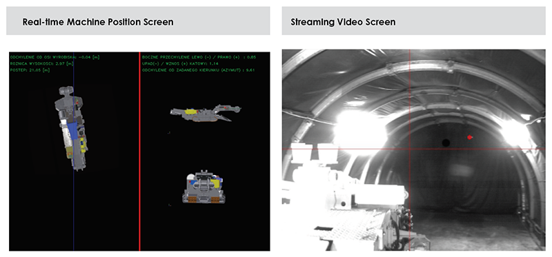
Examples of live machine video and machine position feedback displays are shown below.
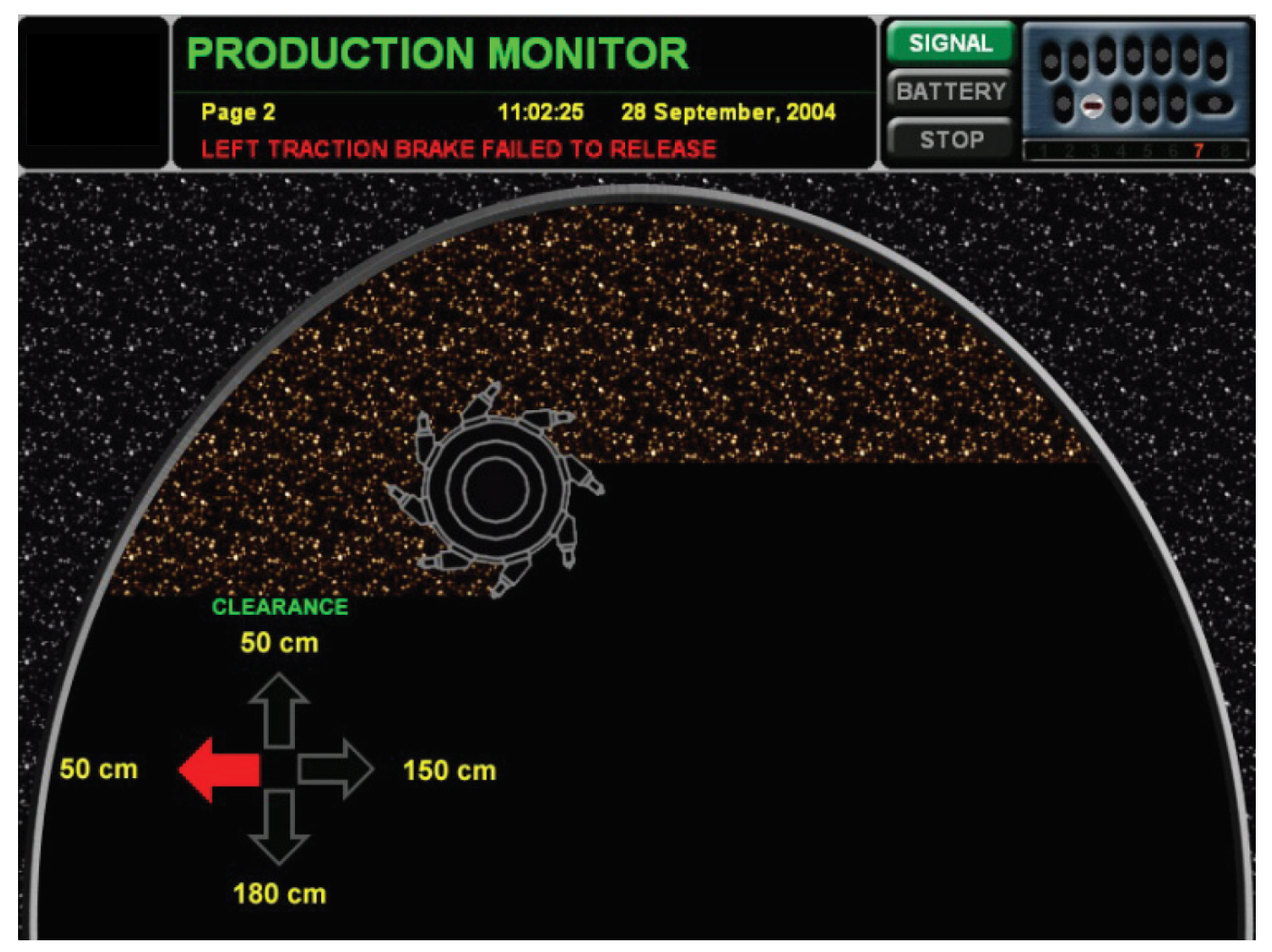
A key feature of this mode of operation is the profile cutting assistance display. The pre-programmed tunnel profile is drawn by the system one of the LCD screens. Also represented is the cutter head. During the cutting operation, the operator can follow the position of the cutter head on this screen so as to ensure that the cutting does not exceed the boundaries of the profile. The display also indicates how much of the profile has been cut and how much ore material remains to be excavated. An example of the profile cutting screen is shown below.
Auto Profile Cut
The Auto Profile Cut mode takes the control of the tunnel profile one step further. In this mode, the operator uses the remote control console to position the machine; using the LCD screen navigation references. The operator then selects the auto cut mode and the machine will then cut the profile automatically. After one pass the automatic cycle stops and the operator can then position the machine again before executing the next auto-cutting operation.
Theory of Operation
The Pempek Underground Guidance and Remote Control System provide a complete solution for machine control, navigation, positioning, monitoring, and data collection.
The key element of the system is its ability to provide accurate and reliable machine navigation positions in real-time.
The navigation system is based on the concept of following the course set by the position and direction of the roof-mounted laser.
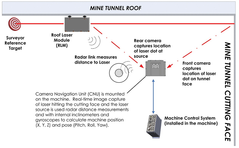
The machine-mounted Laser Navigation Module (L0XP) uses its forward-facing camera to capture real-time video frames of the laser dot striking the tunnel cutting face. The rear-facing camera in the L0XP obtains images of the laser source (emitted from the roof-mounted laser module L0YP).
The video frames captured allow the navigation system to monitor the alignment of the machine with respect to the heading set by the laser beam.
The L0XP also features an internal radar transponder communicating with the roof laser module (L0YP). The radar provides precise distance measurement between the machine and the L0XP. The L0YP also includes a number of other internal sensors; including a gyroscope and inclinometers.
Using information gained from the laser tracking, radar transponder and internal sensors the L0XP can calculate the position of the machine at all times.
This information is provided to the operator back at the control room via a three-dimensional representation of the machine. The machine is drawn in three views that move according to the position of the machine (X, Y, Z coordinates) and the angular pose of the machine (pitch, roll, and yaw).
Displacement transducers installed in the hydraulic cylinders controlling the cutter boom provide the onboard control system with precise position data of the cutter head with respect to the machine frame. Combining this data with the machine position and pose allow the tunnel profile cutting to be accurately monitored and controlled.
System Installation
The system can be readily installed on almost any standard road header or continuous miner. The machine control system is typically installed in a main electrical enclosure. This enclosure provides flameproof protection (Ex d) if required by the mining conditions.
Linear displacement transducers are also required to monitor the position of the cutter head. These devices are normally installed inside the hydraulic cylinders controlling the swing and elevation of the cutter boom.
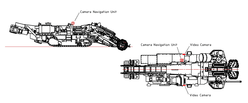
The Laser Navigation Module (L0XP) must be installed on top of the machine and be afforded sufficient free space, both in front and behind, for the internal cameras to see the laser beam.
Finally, a set of video cameras can be installed on the machine to provide real-time streaming video feedback to the control room. The number and arrangement of video cameras depend on a number of factors, including the size of the machine and the mining conditions.
An example of how the equipment might be installed on a typical road header is shown in Figure 10. In this example, the Laser Navigation Module (L0XP) has been offset from the centerline of the machine.
System Calibration
Calibration of the navigation system is a relatively simple process that only needs to be performed each time the cutting face advances far enough to require the roof laser to be moved forward. In most mining situations this would typically be every 20 to 40 meters of tunnel advance.
The first step in the process is for the mine surveyor staff to attach the Roof Laser Module (L0YP) to the ceiling of the tunnel. The L0YP features a forward-pointing laser and backward-pointing laser; both lasers are precisely aligned in the same direction. When the L0YP is installed on ceiling, the surveyor staff ensure that the front pointing laser indicates the correct direction and heading for the development of the tunnel. This is established by ensuring that the laser hits the cutting face at the correct position.
A target can be positioned in the back of the tunnel in an area that is known to be geologically stable. The target is positioned so that the rear-pointing laser hits a known point (“bull’s-eye”) on this target. This target can be checked manually while the tunnel is being developed to monitor if the roof holding the laser shifts due to changing geological
conditions. Such a change in laser position
interferes with the desired tunnel heading. Using the target and rear-pointing laser helps mine staff make corrections for any such event.
The next step is to calibrate the position of the laser dot in the cutting profile. In many cases, it is not possible to position the laser so that the dot is in the exact center of the tunnel profile. Often the dot will be offset from the center; both in the X and Y
dimensions. Mine surveyors determine the X and Y offsets from the true tunnel profile and enter these offsets into the control system on the machine. These offsets are stored in the Laser Navigation Module (L0XP) and are then used for all machine position calculations.
Once these two calibration steps have been performed, the system is ready to track the tunnel navigation of the machine.
